How to Draw a State Chart Diagram
A state diagram is used to represent the condition of the system or part of the system at finite instances of time. It'due south a behavioral diagram and it represents the behavior using finite state transitions. State diagrams are as well referred to as Country machines and State-chart Diagrams. These terms are often used interchangeably. Then simply, a state diagram is used to model the dynamic beliefs of a class in response to time and changing external stimuli. We tin can say that each and every course has a state but we don't model every class using State diagrams. Nosotros prefer to model united states of america with three or more states.
Uses of statechart diagram –
- We use it to state the events responsible for change in country (we do not show what processes cause those events).
- We use it to model the dynamic behavior of the arrangement .
- To understand the reaction of objects/classes to internal or external stimuli.
Firstly let us empathize what are Beliefs diagrams? There are two types of diagrams in UML :
- Structure Diagrams – Used to model the static structure of a system, for example- class diagram, packet diagram, object diagram, deployment diagram etc.
- Behavior diagram – Used to model the dynamic change in the system over fourth dimension. They are used to model and construct the functionality of a system. And so, a behavior diagram but guides us through the functionality of the system using Use case diagrams, Interaction diagrams, Activity diagrams and State diagrams.
Difference between state diagram and flowchart –
The basic purpose of a state diagram is to portray various changes in state of the class and not the processes or commands causing the changes. However, a flowchart on the other hand portrays the processes or commands that on execution alter the land of grade or an object of the class.
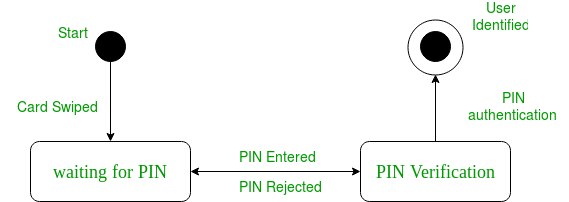
The state diagram above shows the different states in which the verification sub-organisation or class be for a particular organisation.
Basic components of a statechart diagram –
- Initial state – We use a black filled circle represent the initial state of a System or a form.

Figure – initial state annotation - Transition – Nosotros use a solid arrow to stand for the transition or change of control from one land to another. The pointer is labelled with the result which causes the modify in country.

Figure – transition - State – We use a rounded rectangle to stand for a state. A state represents the weather condition or circumstances of an object of a class at an instant of fourth dimension.

Figure – state notation - Fork – We use a rounded solid rectangular bar to represent a Fork notation with incoming arrow from the parent state and outgoing arrows towards the newly created states. Nosotros use the fork note to represent a state splitting into 2 or more concurrent states.
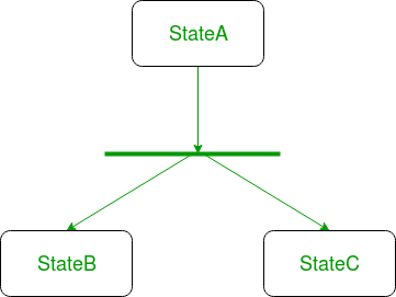
Figure – a diagram using the fork notation - Bring together – We use a rounded solid rectangular bar to represent a Join notation with incoming arrows from the joining states and outgoing arrow towards the common goal country. Nosotros apply the join notation when two or more states concurrently converge into ane on the occurrence of an event or events.
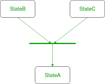
Figure – a diagram using join notation - Self transition – We use a solid pointer pointing dorsum to the state itself to represent a self transition. In that location might be scenarios when the country of the object does not change upon the occurrence of an outcome. We utilise self transitions to represent such cases.
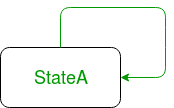
Figure – cocky transition notation - Composite country – We utilize a rounded rectangle to represent a composite state besides.We stand for a land with internal activities using a composite state.
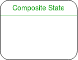
Figure – a state with internal activities - Terminal country – We use a filled circle within a circle annotation to represent the final land in a state machine diagram.

Figure – concluding state notation
Steps to draw a state diagram –
- Identify the initial state and the final terminating states.
- Identify the possible states in which the object tin be (purlieus values respective to different attributes guide united states in identifying unlike states).
- Label the events which trigger these transitions.
Example – land diagram for an online society –
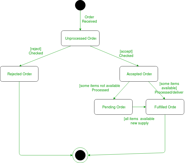
The UMl diagrams we draw depend on the system we aim to represent. Hither is just an instance of how an online ordering arrangement might look like :
- On the event of an order being received, we transit from our initial land to Unprocessed order state.
- The unprocessed gild is then checked.
- If the order is rejected, we transit to the Rejected Order country.
- If the order is accepted and nosotros have the items available we transit to the fulfilled social club state.
- Even so if the items are not available we transit to the Pending Lodge state.
- After the order is fulfilled, we transit to the final state. In this case, we merge the two states i.due east. Fulfilled club and Rejected order into one final state.
Notation – Here nosotros could have also treated fulfilled guild and rejected order as last states separately.
Reference –
State Diagram – IBM
This article is contributed by Ankit Jain . If you like GeeksforGeeks and would like to contribute, you can also write an commodity using contribute.geeksforgeeks.org or mail your article to contribute@geeksforgeeks.org. See your commodity appearing on the GeeksforGeeks principal page and aid other Geeks.
Please write comments if you notice annihilation incorrect, or you want to share more information about the topic discussed above.
Source: https://www.geeksforgeeks.org/unified-modeling-language-uml-state-diagrams/
0 Response to "How to Draw a State Chart Diagram"
Post a Comment